

NFP-GM37-BL3525
37mm Brushless Gear Motor
Technical information for your next design.
Review the specifications and drawings for the exact configuration. Match the mechanical envelope and operating requirements to your assembly.
- Rated voltage
- 12V / 24V DC
- Rated speed
- 3rpm – 700rpm
- No-load speed
- 4.5rpm – 930rpm
- Weight
- 160g – 180g
01 / TECHNICAL REFERENCE
Reversible Brushless Motors with Gearbox Performance
The characteristics of this brushless geared motor include stable lifespan, about 3 – 5 times that of brushed motors, wide operating voltage range, low noise, high torque, stable and reliable performance, bi-directional rotation capability, emergency stop upon power loss, speed control, and speed measurement output.
Electrical & performance data
| Rated Voltage | 12V / 24V DC |
|---|---|
| No-load Speed | 4.5rpm – 930rpm |
| No-load Current | ≤0.1A / ≤0.13A |
| Rated Speed | 3rpm – 700rpm |
| Current | ≤0.3A / ≤0.4A |
| Torque | 0.04N.m – 3N.m |
| Max Output Power | 2W / 8W |
Mechanical & operating data
| Model | NFP-GM37-BL3525 |
|---|---|
| Shaft Diameter | 6mm |
| Shaft Length | 21mm |
| D-cut Shaft Length | 12mm |
| Rotation | CW / CCW |
| Weight | 160g – 180g |
Model: NFP-GM37-BL3525-1260, 12V DC
| Ratio | No-load Speed | No-load Current | Rated Speed | Rated Current | Rated Torque | Stall Torque | Stall Current |
|---|---|---|---|---|---|---|---|
| 6.3:1 | 465rpm | ≤0.1A | 330rpm | ≤0.3A | 0.04N.m | ≥0.1Nm | ≤3A |
| 10:1 | 290rpm | ≤0.1A | 220rpm | ≤0.3A | 0.07N.m | ≥0.17Nm | ≤3A |
| 18.8:1 | 155rpm | ≤0.1A | 115rpm | ≤0.3A | 0.12N.m | ≥0.3Nm | ≤3A |
| 30:1 | 95rpm | ≤0.1A | 72rpm | ≤0.3A | 0.2N.m | ≥0.5Nm | ≤3A |
| 50:1 | 57rpm | ≤0.1A | 42rpm | ≤0.3A | 0.35N.m | ≥0.7Nm | ≤3A |
| 90:1 | 32rpm | ≤0.1A | 24rpm | ≤0.3A | 0.6N.m | ≥1.2Nm | ≤3A |
| 150:1 | 20rpm | ≤0.1A | 14rpm | ≤0.3A | 1N.m | ≥1.5Nm | ≤3A |
| 260:1 | 11rpm | ≤0.1A | 8rpm | ≤0.3A | 1.5N.m | ≥2Nm | ≤3A |
| 450:1 | 6rpm | ≤0.1A | 4rpm | ≤0.3A | 2.5N.m | ≥3Nm | ≤3A |
| 630:1 | 4.5rpm | ≤0.1A | 3rpm | ≤0.3A | 3N.m | ≥3Nm | ≤3A |
                    Note: all reduced
                    no-load speeds
                    have a tolerance of ±15%.
Model: NFP-GM37-BL3525-2460, 24V DC
| Ratio | No-load Speed | No-load Current | Rated Speed | Rated Current | Rated Torque | Stall Torque | Stall Current |
|---|---|---|---|---|---|---|---|
| 6.3:1 | 930rpm | ≤0.13A | 700rpm | ≤0.4A | 0.09N.m | ≥0.2Nm | ≤3A |
| 10:1 | 585rpm | ≤0.13A | 445rpm | ≤0.4A | 0.14N.m | ≥0.35Nm | ≤3A |
| 18.8:1 | 310rpm | ≤0.13A | 235rpm | ≤0.4A | 0.25N.m | ≥0.65Nm | ≤3A |
| 30:1 | 195rpm | ≤0.13A | 145rpm | ≤0.4A | 0.4N.m | ≥1Nm | ≤3A |
| 50:1 | 117rpm | ≤0.13A | 85rpm | ≤0.4A | 0.7N.m | ≥1.5Nm | ≤3A |
| 90:1 | 65rpm | ≤0.13A | 48rpm | ≤0.4A | 1.2N.m | ≥2.5Nm | ≤3A |
| 150:1 | 39rpm | ≤0.13A | 29rpm | ≤0.4A | 2.1N.m | ≥3Nm | ≤3A |
| 260:1 | 23rpm | ≤0.13A | 17rpm | ≤0.4A | 3N.m | ≥3Nm | ≤3A |
| 450:1 | 13rpm | ≤0.13A | 9rpm | ≤0.4A | 3N.m | ≥3Nm | ≤3A |
| 630:1 | 9rpm | ≤0.13A | 6rpm | ≤0.4A | 3N.m | ≥3Nm | ≤3A |
                    Note: all reduced
                    no-load speeds
                    have a tolerance of ±15%.
02 / TECHNICAL REFERENCE
Micro Geared Brushless DC Motors Outline Drawing
Built-in Hall driver board, which can operate directly when powered on, without the need for external driver circuits.
NFP-GM37-BL3525 bldc motors dimensions
Open full size ↗
03 / TECHNICAL REFERENCE
All Metal Brushless Gear Motor Bracket Diagram
DC brushless gear motor widely used in smart home appliances, robots, smart machines, electric windows, electric doors, automatic rotating equipment, PTZ, food packaging, manipulators, communication equipment, printing equipment, vehicle industry, medical equipment, security equipment, office automation, model aircraft, and automotive electronics.
NFP-JGB37-3525 bldc gear motor wiring diagram
Open full size ↗
04 / TECHNICAL REFERENCE
Micro DC Brushless High Torque Reducer Wiring Diagram
Red Wire: Positive pole of motor power supply +, polarity must not be reversed.
Black Wire: Negative pole of motor power supply -, polarity must not be reversed.
White Wire: Direction control wire. When disconnected, the motor rotates in one direction; connect to the negative terminal along with the black wire for reversing.
Blue Wire: PWM speed control wire, connect to a 0 – 5V pulse width modulator.
Yellow Wire: FG signal wire, outputs 9 square wave pulses. Speed can be determined by detecting the frequency of the pulses, similar to a single-wire encoder.
05 / TECHNICAL REFERENCE
Mounting Bracket Outline Drawing
37mm mounting bracket size outline drawing
Open full size ↗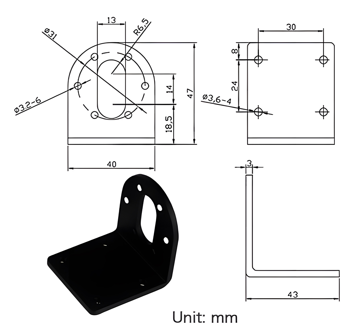
ENGINEERING ENQUIRY
Discuss NFP-GM37-BL3525.
Send the model reference, available space, electrical requirements, operating conditions and expected quantity.