2–2 phase excitation
18° sequenceCW ← → CCW
| Phase | 1 | 2 | 3 | 4 |
|---|---|---|---|---|
| A | H | H | L | L |
| A− | L | L | H | H |
| B | L | H | H | L |
| B− | H | L | L | H |

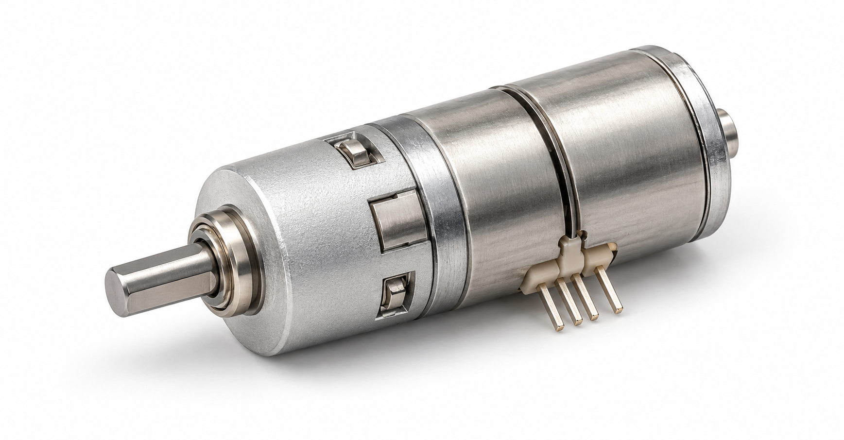
GB06 SERIES / 5.14:1 REDUCTION
Compact motion. Precisely geared.
A two-phase bipolar stepper motor paired with a single-stage planetary gearbox. A 6 mm cylindrical body and four-pin connection for compact positioning mechanisms.
Part no. GB06-5.14-MD16001-1-SM
01 / TECHNICAL DATA
Electrical, drive and mechanical data for the 5.14:1 single-stage configuration.
| Rated voltage | 4.8 V DC |
|---|---|
| Coil resistance | 26.5 Ω ±7% |
| Number of phases | 2 |
| Drive mode | Bipolar |
| Excitation method | 2-phase excitation |
| Specified step angle | 3.5019° / step |
| Operating temperature | −20 to +50 °C |
| Gear ratio | 5.14:1 |
|---|---|
| Gear stages | 1 |
| Pull-in torque | ≥5.2 g·cm at 500 PPS |
| Pull-out torque | ≥7 g·cm at 500 PPS |
| Max. starting frequency | 1,500 PPS min. |
| Max. response frequency | 2,500 PPS min. |
| Axial gap | 0.3 max. (drawing value) |
Torque values are specified at 500 pulses per second. Starting and response frequencies are minimum specified limits. Use the excitation tables below together with the original drawing when selecting the drive. Noise-test setup in the source: 10 cm from the reducer, with 31 dB ambient noise.
02 / MECHANICAL REFERENCE
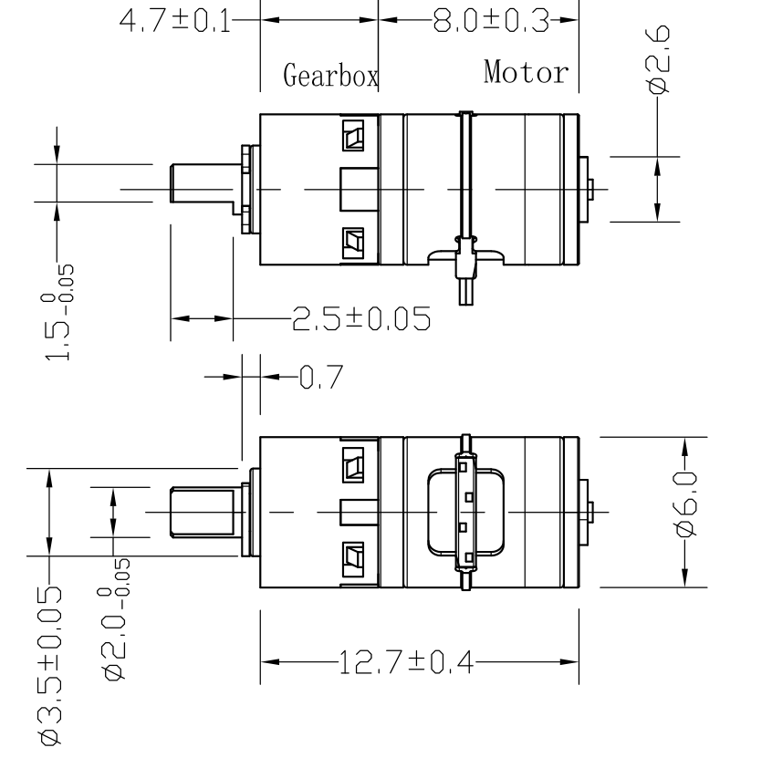
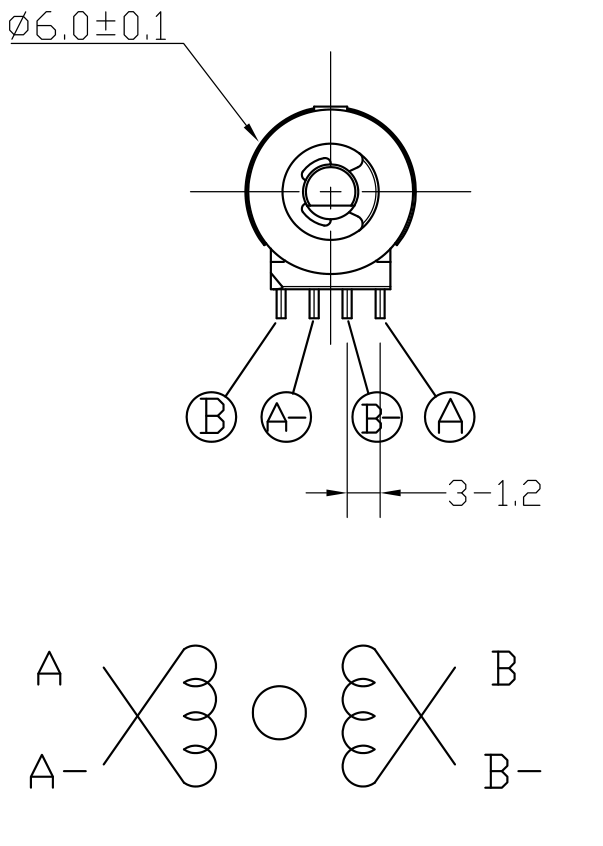
Original drawing views retain the source dimensions, tolerances and terminal identification. Dimensions in mm.
03 / DRIVE REFERENCE
Both sequences are shown in full. Read the terminal order from the front view above; the two source tables use different direction labels.
CW ← → CCW
| Phase | 1 | 2 | 3 | 4 |
|---|---|---|---|---|
| A | H | H | L | L |
| A− | L | L | H | H |
| B | L | H | H | L |
| B− | H | L | L | H |
CCW ← → CW
| Phase | 1 | 2 | 3 | 4 | 5 | 6 | 7 | 8 |
|---|---|---|---|---|---|---|---|---|
| A | H | OFF | L | L | L | OFF | H | H |
| A− | L | OFF | H | H | H | OFF | L | L |
| B | L | L | L | OFF | H | H | H | OFF |
| B− | H | H | H | OFF | L | L | L | OFF |
The source labels the 2–2 phase sequence as 18° and the 1–2 phase sequence as 9°. Its specification table separately gives 3.5019° per step. These labels are preserved as supplied.
04 / DESIGN INTEGRATION
Check the Ø6 mm body, output shaft geometry, front bearing boss and terminal clearance against the original drawing.
Review dimensions ↑Match a bipolar driver to the 4.8 V winding and 26.5 Ω coil resistance. Check phase mapping before powering the motor.
Review excitation ↑Evaluate torque, pulse rate and start-up behavior in your assembly. Share the load, duty cycle and expected quantity with our team.
Discuss your application ↗ENGINEERING ENQUIRY
Send your load, pulse rate, available space and target quantity. Reference part GB06-5.14-MD16001-1-SM.
Product image: AI-generated illustrative render based on the outline drawing. Dimensions and electrical data follow the original specification.