Sequence of Excitation
2–2 phase, 18° drive sequenceCW ← → CCW
| Phase | 1 | 2 | 3 | 4 |
|---|---|---|---|---|
| A | H | H | L | L |
| A− | L | L | H | H |
| B | L | H | H | L |
| B− | H | L | L | H |

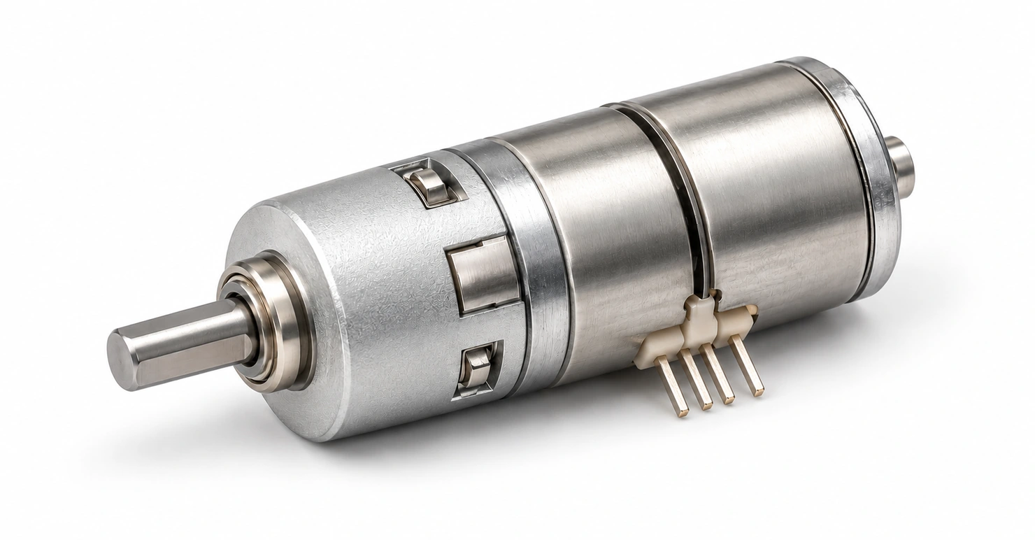
GB06-700-MD16001-1-SM
Compact motion. Precisely geared.
A 6 mm two-phase stepper motor with a 4-stage planetary gearbox and a 699.55:1 transmission ratio.
Part / series no. GB06-700-MD16001-1-SM
01 / TECHNICAL DATA
Electrical performance, construction and operating data for the specified configuration or motor family.
| Rated voltage | 4.8 V DC |
|---|---|
| Coil resistance | 26.5 Ω ±7% |
| Number of phases | 2 |
| Excitation method | 2–2 phase excitation |
| Drive mode | Bipolar constant-voltage drive |
| Maximum starting frequency | 1500 pps min |
| Maximum response frequency | 2500 pps min |
| Operating temperature | −20 to +50 °C |
|---|---|
| Step angle | 0.0257°/step |
| Pull-in torque | 460 g·cm min at 500 pps |
| Pull-out torque | 626 g·cm min at 500 pps |
| Axial play | 0.3 mm max |
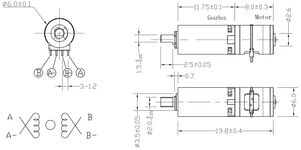
| Body diameter | 6.0 ±0.1 mm |
| Assembly body length | 19.8 ±0.4 mm |
| Gearbox length | 11.75 ±0.1 mm |
| Motor length | 8.0 ±0.3 mm |
| Shaft extension | 2.5 ±0.05 mm |
| Shaft diameter | 2.0 +0/−0.05 mm |
| Shaft flat dimension | 1.5 +0/−0.05 mm |
02 / MECHANICAL REFERENCE
English drawing labels with original dimensions and tolerances. Open the image to inspect the full drawing.
03 / DRIVE REFERENCE
CW ← → CCW
| Phase | 1 | 2 | 3 | 4 |
|---|---|---|---|---|
| A | H | H | L | L |
| A− | L | L | H | H |
| B | L | H | H | L |
| B− | H | L | L | H |
CCW ← → CW
| Phase | 1 | 2 | 3 | 4 | 5 | 6 | 7 | 8 |
|---|---|---|---|---|---|---|---|---|
| A | H | OFF | L | L | L | OFF | H | H |
| A− | L | OFF | H | H | H | OFF | L | L |
| B | L | L | L | OFF | H | H | H | OFF |
| B− | H | H | H | OFF | L | L | L | OFF |
Use the terminal positions shown in the original drawing. H = high, L = low; OFF = unenergized.
04 / DESIGN INTEGRATION
Review the gearbox dimensions, mounting interface, shaft geometry and connection clearance in the outline drawing.
Review dimensions ↑Specify the supply voltage, speed, torque and duty cycle. Use the complete part code when selecting a configuration.
Review original data ↗Check start-up behavior, load, clearances and operating temperature in the intended mechanism.
Discuss your application ↗ENGINEERING ENQUIRY
Send your operating requirements and expected quantity. Reference GB06-700-MD16001-1-SM.
Product image: AI-generated illustrative render based on the assembly drawing. Exact dimensions and variant details follow the technical drawing and specification tables.