Confirm the envelope.
Review the gearbox dimensions, mounting interface, shaft geometry and connection clearance in the outline drawing.
Review dimensions ↑
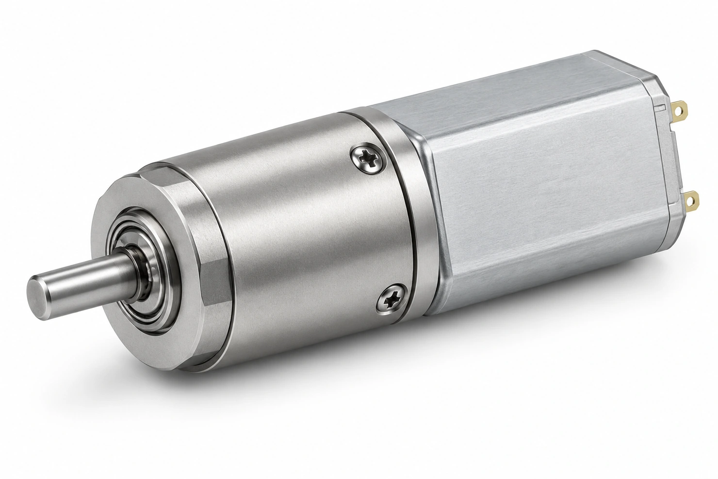
GB10-4-DZ24003-1-M
Compact motion. Precisely geared.
10 mm metal planetary gearbox with an M20 brushed DC motor, offered in 14 reduction ratios. Rated motor voltage is 3.0 V DC.
Part / series no. GB10-4-DZ24003-1-M
01 / TECHNICAL DATA
Electrical performance, construction and operating data for the specified configuration or motor family.
| Rated voltage | 3.0 V DC |
|---|
| Gearbox material | Metal |
|---|---|
| Noise | ≤47 dB |
| Maximum allowable torque | 1 kg·cm |
| Instantaneous allowable torque | 2 kg·cm |
| Output-shaft radial load | ≤2 N |
| Backlash | ≤3° |
| Output-shaft diameter | 2.0 +0/-0.01 mm |
| Output-shaft extension | 7.0 ±0.2 mm |
| Output-shaft flat length | 4.0 ±0.05 mm |
| Output-shaft flat dimension | 1.5 +0/-0.05 mm |
| Gearhead across flats | 8.8 -0.05/-0.1 mm |
| Gearhead diameter tolerance | 10.0 +0/-0.1 mm |
02 / MECHANICAL REFERENCE
English drawing labels with original dimensions and tolerances. Open the image to inspect the full drawing.

03 / SELECTION DATA
Select the complete motor code together with the required voltage, speed and torque. Values and units follow the original specification.
| Model | Reduction ratio (:1) | Rated voltage (V DC) | No-load speed (rpm) | No-load current (mA) | Rated speed (rpm) | Rated current (mA) | Rated torque (g·cm) | Stall current (mA) | Stall torque (g·cm) | Gearbox length L (mm) | Overall length L1 (mm) |
|---|---|---|---|---|---|---|---|---|---|---|---|
| GB10-4-DZ24003-1-M | 4 | 3.0 | 3000 | 50 | 2050 | 120 | 6 | 300 | 15 | 9.7 | 24.7 |
| GB10-6-DZ24003-1-M | 6 | 3.0 | 2050 | 50 | 1300 | 120 | 9 | 300 | 22 | 9.7 | 24.7 |
| GB10-13-DZ24003-1-M | 13 | 3.0 | 845 | 50 | 570 | 120 | 18 | 300 | 46 | 12.8 | 27.8 |
| GB10-19-DZ24003-1-M | 19 | 3.0 | 570 | 50 | 380 | 120 | 27 | 300 | 69 | 12.8 | 27.8 |
| GB10-28-DZ24003-1-M | 28 | 3.0 | 385 | 50 | 260 | 120 | 41 | 300 | 100 | 12.8 | 27.8 |
| GB10-46-DZ24003-1-M | 46 | 3.0 | 235 | 60 | 150 | 120 | 59 | 300 | 148 | 15.9 | 30.9 |
| GB10-69-DZ24003-1-M | 69 | 3.0 | 158 | 60 | 107 | 120 | 87 | 300 | 220 | 15.9 | 30.9 |
| GB10-102-DZ24003-1-M | 102 | 3.0 | 105 | 60 | 72 | 120 | 130 | 300 | 325 | 15.9 | 30.9 |
| GB10-151-DZ24003-1-M | 151 | 3.0 | 72 | 60 | 48 | 120 | 190 | 300 | 480 | 15.9 | 30.9 |
| GB10-168-DZ24003-1-M | 168 | 3.0 | 65 | 60 | 44 | 120 | 190 | 300 | 470 | 19 | 34 |
| GB10-249-DZ24003-1-M | 249 | 3.0 | 44 | 60 | 29 | 120 | 280 | 300 | 700 | 19 | 34 |
| GB10-368-DZ24003-1-M | 368 | 3.0 | 29 | 60 | 20 | 120 | 400 | 300 | 1000 | 19 | 34 |
| GB10-546-DZ24003-1-M | 546 | 3.0 | 20 | 60 | 13 | 120 | 600 | 300 | 1500 | 19 | 34 |
| GB10-809-DZ24003-1-M | 809 | 3.0 | 13 | 60 | 9 | 120 | 900 | 300 | 2200 | 19 | 34 |
04 / DESIGN INTEGRATION
Review the gearbox dimensions, mounting interface, shaft geometry and connection clearance in the outline drawing.
Review dimensions ↑Specify the supply voltage, speed, torque and duty cycle. Use the complete part code when selecting a configuration.
Review original data ↗Check start-up behavior, load, clearances and operating temperature in the intended mechanism.
Discuss your application ↗ENGINEERING ENQUIRY
Send your operating requirements and expected quantity. Reference GB10-4-DZ24003-1-M.
Product image: AI-generated illustrative render based on the assembly drawing. Exact dimensions and variant details follow the technical drawing and specification tables.